
Short answer: a ground and polished screw element presents a smoother flow path. Material slips over the flight instead of being dragged across tool marks, drive energy falls, and abrasive particles have fewer pits to lodge in, so both the element and the barrel wear more slowly.
Two elements can be dimensionally identical — same profile, same lead, same length — and still behave differently in the barrel. The difference is the surface. A milled flight carries tool marks: a series of fine ridges running across the flow direction. A ground and polished flight carries a continuous, directionally aligned surface. The melt sees a different wall, and the difference shows up in three places: how the material flows, how much energy the drive consumes, and how fast the part wears.
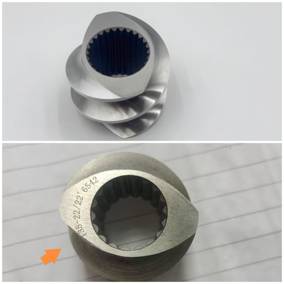
Most screw elements are milled first, because milling is the fastest way to remove stock and generate the helical form. The question is what happens after milling. An element that leaves the machine at the milling stage carries the cutter's footprint: ridges across the flight face, a slightly torn edge on the flight crest, and a surface that varies along the length of the part.
Profile grinding follows the same helix with a formed wheel, removing the milling footprint and leaving a surface aligned with the direction of material flow. Polishing goes one step further, reducing the remaining micro-roughness until the flight reflects light as a continuous surface rather than scattering it.
| Process | Typical Ra | What it means in the barrel |
|---|---|---|
| Milling only | 1.6–3.2 µm | Visible tool marks; melt drags across the ridges |
| Profile grinding | 0.4–0.8 µm | Aligned surface; clean wiping action against the barrel wall |
| Grinding plus polishing | 0.1–0.4 µm | Near-mirror flight; minimum drag and minimum adhesion |
A polymer melt does not slide over a surface like water over glass. It forms a boundary layer, and that layer is sensitive to the wall it touches. Ridges running across the flow direction act as a series of small dams: material accelerates over each crest and decelerates into each trough, and the boundary layer thickens. On a polished flight the same material moves in a more uniform sheet.
The practical symptom is not dramatic. It appears as slightly higher pressure build-up in the metering zone, a marginally wider residence-time distribution, and a tendency for heat-sensitive compounds to discolour in the corners where the boundary layer is slowest.
Every element in the barrel is a pump, and every pump has a friction loss. Roughness adds to that loss because the drive has to overcome the extra drag of the boundary layer as well as the work of conveying and mixing. Ground and polished flights reduce that parasitic component.
This is why the energy effect is easiest to see on lines that run continuously at high screw speed: the drag term scales with surface speed, so a smoother flight saves more energy the faster the machine turns. It is a small effect per element, but a screw set has dozens of them, and the line runs for years.
Roughness accelerates wear through two mechanisms that reinforce each other. First, pits and troughs trap abrasive particles — glass fibre fragments, mineral filler, pigment agglomerates — and hold them against the surface instead of letting them pass. A trapped particle becomes a third body that grinds both the element and the barrel. Second, the micro-notches at the base of tool marks are stress raisers, and under cyclic loading they can initiate the fine surface cracks that later spall.
A polished surface has neither the traps nor the notches. That is why a polished element does not just look better on the bench; it keeps its geometry longer in service.
| Zone | Why finish matters there |
|---|---|
| Melting zone | Highest surface speed and the first contact with unmelted granules — drag is maximum here |
| Dispersion blocks | Trapped particles do the most damage in the high-shear gap |
| Metering and discharge | Pressure build-up is most sensitive to boundary-layer losses |
| Barrel bore | The flight wipes the bore; a rough flight abrades the liner it runs against |
Our elements are cut, heat-treated, then profile-ground on a five-axis machine that follows the same helix as the OEM drawing, so the self-wiping geometry is preserved while the milling footprint is removed. Polishing follows as a separate operation, with the flight face, the flight crest and the root treated in sequence — the crest matters most because it is the surface that runs closest to the barrel wall.
The bore and the end faces are finished to the same standard. A mirror-polished flight on a rough bore is a half-finished job: the bore is where the shaft spline sits, and a poor fit there produces fretting and misalignment that no amount of flight polishing will fix.
Polishing improves flow and wear resistance, but it cannot rescue a wrong geometry, an undersized flight or a soft steel grade. It is also not a substitute for coating: on highly abrasive duty, a PVD or HVOF coating on a ground surface outperforms a polished uncoated one. The sensible order is geometry first, then steel grade, then coating or finish — each layer builds on the one below.
The same finish is one of the cheaper routes to cutting specific energy per kilogram.
For most compounding duty, profile grinding to roughly Ra 0.4 to 0.8 micrometre is the baseline, and polishing to Ra 0.1 to 0.4 micrometre is the upgrade. The flight crest and the bore matter most, because those are the surfaces that run against the barrel and carry the shaft fit.
Yes, through reduced drag in the boundary layer. The effect scales with surface speed, so it is largest on high-speed lines and smallest on slow ones. It is a modest per-element saving that accumulates across a full screw set running continuously.
No, when it is done as a finishing operation after grinding. Polishing removes micrometres, not millimetres. The risk only appears when polishing is used to hide a badly milled profile, which is why the grinding step has to be correct first.
Yes. Coatings are applied to a ground surface and the polish can precede or follow depending on the coating process. For very abrasive duty the combination of a ground substrate and a hard coating is more effective than polishing alone.
Look at the flight crest under a light: a milled crest scatters light and shows a visible line of tool marks, a ground and polished crest reflects a continuous highlight. Ask for an Ra reading on the finished part as well.